Wednesday, November 11, 2015

Technical challenges of small gas turbines

Part 4

 Note: If you are un familiar with the small gas turbines, they are a niche sector of small to medium size jet engines. For an introduction, see this post.

In this post, let us look at the problems faced in the design of the turbine blades and turbine disk of the small gas turbines.
The turbine blades, have to face the hot gases coming from the combustor. The material in which these blades are made determines the TET (Turbine entry temperature = exit temperature of the gases from the combustor).
Any more hotter, the TET exceeds the material limits of the turbine blades and the turbine blows up.
And you have to try keep the TET as high as possible so that you don't lose thermal efficiency.
in a study on methanol fuelled gas turbines, the authors have published a figure that shows the increase in thermal efficiency as TET increases.

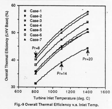
Increase in thermal efficiency as TET increases, from Asahi-net.

This desire to push the TET as high as possible has lead to several advances in turbine blade cooling. One common technique is to use serpentine flow passages inside the turbine blade. These passages effectively make the turbine blade hollow. Air ducted from compressor outlet flows through these hollow blades. The outer skin of the turbine blade faces the hot combustor exit gases (around 1600 degree Celsius) and the inner skin faces the relatively cooler gas (around 400 degree Celsius). This cooler gas carries some of the heat energy from the hot gases and hence keeps the turbine blade temperature from exceeding its limits.

The problem in implementing these passages in SGT blades is that the blades are too small. Hence it is difficult to machine such intricate passages inside the turbine blade. A figure showing a larger engine's turbine blade and SGT's turbine blade side by side, gives an idea of the level of intricate machining required in SGT blades.
Relative sizes of SGT and large blades, from "The History of North American Small Gas Turbine Aircraft Engines"
The next problem is that of thermal stresses in the turbine disk. As you can see in the image below, the periphery of the turbine disk will be at the temperature of the hot gases. Say 1600 degree celsius. The hub of the turbine disk, where the shaft attaches to the disk, is at a much lower temperature, around 300 degree Celsius.

A turbine disk with blades, from codesmith.com
This difference in temperature causes thermal stresses. The difference in temperature is same for both SGT and large engines, but he distance over which this change in temperature happens is much smaller in a SGT.
This smaller distance gives higher stresses for the same temperature change.

Demonstrating with an example:

The formula for radial stress in a disk of uniform thickness (E = Youngs modulus, α = coefficient of expansion ) is

In the above equation, the constants A and B can be found by imposing the condition that the radial stress has to be 0 at the inner and outer radius. Using this equation, the radial stress distribution of two turbine disks have been computed and plotted below. The temperature at the inner radius of both the disks is 300 degree Celsius and the temperature at the outer radius is 1600 degree Celsius. The SGT disk is smaller, with the inner radius of 3 cm and outer radius of 10 cm. The larger turbine disk has a inner radius of 10 cm and outer radius of 30 cm. The graph below shows the level of radial stress along the radius of the turbine disk.

 
Smaller engines experience higher stresses
 It can be seen that the SGT disk faces higher thermal stresses than the larger turbine disk, though only marginally. In the next article, let us look at the problems faced in the design of the turbine shaft and casings for the small gas turbine.

 Technical challenges of small gas turbines 

 Part 3


 Note: If you are un familiar with the small gas turbines, they are a niche sector of small to medium size jet engines. For an introdduction, see this post.

The combustor sits behind the compressor and heats up the compressed air so that the energy content of the air rises, of which some will be extracted back by the turbine. The combustor is second only to the compressor in terms of design complexity and the SGT's minuscule size compounds the problems even higher.  The first problem is in getting the fuel inside the combustor. 

Like in ordinary Kerosene fueled stoves, complete combustion happens when the fuel stream is broken down in to fine droplets. This is so that for a given volume of fuel, smaller and more the number of droplets, more will be the surface area. More the surface area, more is the area of contact with Oxygen and the droplets vaporize faster and finally the vaporized fuel burns better. 


 Moreover, this atomized fuel has to be introduced into the combustor at multiple locations. This is so that the fuel distribution in the combustor is uniform. A spray bar, with multiple nozzles for injection is usually used in for injection in this manner. 
Multiple fuel injection nozzles on a spray bar.
For an SGT, the fuel flow rate in to the combustor is already low. Divide that into multiple nozzles, and the fuel flow through each nozzle becomes even lower. But in order to get good atomization, the nozzle orifice has to be very small so that the fuel breaks up into fine drops as it leaves the nozzle. Designing an orifice for such low fuel flow rates as encountered in SGT's result in very delicate orifices that get clogged with carbon deposits easily. 
Fuel breaking up into tiny drops as it is pushed out of the tiny orifice. Image from jrthomson
This major problem precluded the use of fuel injecting nozzles in small gas turbines and a very innovative way of injecting fuel into the combustor was developed by engineers of Teledyne CAE. 
Lets look at slinger combustors next.

Edit: I couldn't find any publicly available resources that describe the operation of the slinger combustor and I can't give out any propreitary knowledge that is not in open domain.
So let us conclude this post on technical challenges regarding the combustor problems of SGTs by noting that slinger combustors offer solution to the problem.

 Technical challenges of small gas turbines 

 Part 2
 

 Note: If you are un-familiar with the small gas turbines, they are a niche sector of small to medium size jet engines for missiles and drones. For more information, see this post

 In continuation of our rundown of the technical challenges that were faced by the designers SGT's, next in line are the clearance and smoothness (tolerance).

 The clearance problem is pretty easy to understand. You use a compressor to increase the pressure of the air going in to the combustion chamber. Just behind the compressor, there is high pressure air. In front of the compressor, there is ambient air, at a pleasant 0.9 bar pressure. And there is a tiny gap between the rotating compressor and the stationary casing of the compressor. This gap is there so that the compressor rotor doesn't rub the casing when it is rotating like crazy. But the high pressure air, which doesn't know the real purpose of the clearance gap,  sees it as a way to get out of the high pressure situation. It goes through this clearance, back into the lower pressure area in front of compressor. 
A simple schematic showing possible reverse flow location 

 All this means that whatever fuel you spent in compressing the leaked air is a waste of money.The problem is more severe for SGT's than for large gas turbines. This is because the leakage losses depend on the ratio of the clearance gap to blade height. SGT compressor blades, are small. This  means that for the same clearance gap, losses faced by SGT may be too much, while the losses of a large gas turbine may be tolerable.
For the same clearance, the clearance to blade height ratio is much higher for SGT. This means more loss :(

 This brings us to the next issue. The one of smoothness: aka manufacturing tolerances. The manufacturing tolerances are no where more critical than the compressor air foils and the seals. These tolerances are specified as a fraction of the major dimension of the part.For a wide chord fan blade of a large turbofan such as Trent 800, the tolerances can be relatively high , in the order of 100 microns or so. Tolerances of trailing edges of air foils are of the order of 3 hundredths of an inch(Leyes and Fleming, Page 22). This is OK, because the major dimension, the chord of the blade, is large and the ratio of tolerance to chord is still small enough that you can live with it. However, try maintaining the same ratio in a SGT compressor airfoil and suddenly you are in need of machinery and skilled labour who can give very close tolerances , sometimes of optical grade quality. It is not that these equipment are not available. It is just that when you are making an engine that is going to blow up in one hour, investing so much in such high precision components is difficult to swallow. It is usually termed in gentlemanly terms in books as "undue costs". 

Compressor blades and seals have very low tolerances of manufacture (image from power-technology.com)
The next major problem faces by the pioneers has to do with the combustor. Let us look at that next. 

Technical challenges of small gas turbines 

Part 1

The Williams WR24 samll gas turbine,  (image from blueyonder.co.uk)

Commercially, the main challenge face by gas turbines was the competition from the cheaper and more reliable reciprocating engines. These Internal Combustion(IC) engines were well capable of producing the power required for unmanned drones and target practice vehicles. It was the small gas turbines, (SGT's) that were encroaching into the territory long held by IC engines. This being said, it is not that the challenges faced by fore-runners of the SGT industry (such as Westinghouse and Fladder inc.) are only from the market.
They faced quite a few challenges on the technical front as well. As Hans Von Ohain rightly put,

 ”.. the small gas turbine could not be considered simply as a scaled down version of a large gas turbine”.

The first problem the SGT faces is against physics itself. To understand what begrudge physics has against the SGT, we need to look at the Reynolds's number. 

Reynolds's number and Mach number are the primary parameters that provide an idea of the state of the flow. While Mach number is quite common, Reynolds's number is usually an  unfamiliar term to non-mechanical engineers. However this parameter is very much intrinsic to all fluid flow. It gives an idea of the dominance of the momentum of the fluid, that wants to keep going, over the sticky viscous forces that don't want the fluid to flow freely. If a blob of water is flowing very fast, or if that blob is very big, its momentum is high and consequently it will be very hard to stop that blob of water from moving ahead. It will have a large Reynolds's number. Consequently, if our blob was made of molten tar (am referring to the stuff used in laying roads) instead of water, it would move or should I say ooze, very slowly, at a leisurely pace. Its movement is retarded by the sticky forces, that only let it move slowly, but in a highly ordered fashion. 
Flowing tar, highly ordered flow. (from www.pavingexpert.com)
What this Reynolds's number has to do with the success of the SGT? Everything actually. It turns out that small gas turbines, with the small fluid flows through them, usually have low Reynolds's number. And lower the Reynolds's number, lower will be your efficiency (Don't ask me why. Ask the people at NASA. They figured this out way back in 1949). The engine will still produce as much thrust as you ask out of it, but it will gulp down more fuel in doing so. More fuel you need for thrust, more fuel you need to carry and the bigger your engine needs to be to carry the more fuel and more fuel for the bigger engine.. you get the idea. So the lower efficiency for smaller gas turbines mean that the odds are usually in favor of the large engines.
This is not the only problem. There are much more technical hurdles that need to be overcome. Most prominent among them are the leakage effects and smoothness requirement. Let's see them in detail in the next post. 

History of small gas turbines: The Commercial challenge.


The history of small gas turbines (SGT), like many, has been one full of ups and downs. There have been periods of active development large scale production and   periods where engineers forget that such a category of gas turbines exist totally. On the technical front, these SGTs pose a  set of challenges different from that of the larger engines. The main source of most the issues, as expected, is their diminutive size. Overall, these SGTs are no less complicated than their larger counter parts, if not more.

The definition of small gas turbines, or SGTs, has been evolving with time. What is a medium gas turbine in our generation is a small gas turbine in the next generation. This is mainly because we engineers have been squeezing ever more mass flow into these small machines and extracting more and more thrust Out of them. In the 1950's engines giving up to 900 shaft horse power were considered small. By the late 1990's the definition of SGT's included engines producing up to 6000 shp. A point to note here is that the large gas turbines of 1950's have become small gas turbines by 1990. The predominant application of these SGTs has primarily been target practice drones and a few military trainer aircraft. Target practice drones, for those who don't know, are basically small unmanned aircraft that are flow via radio so that the anti-aircraft gun crews can shoot them down for practice. The Ryan "Firebee" is one of the most successful target practice drones that used a SGT. 
The popular Firebee drone, with a Continental-J69 engine, image from wikipedia.


When introduced, these gas turbines faced an interesting set of commercial challenges. One main challenge they faced was that, they had a huge competition from piston engines of the time. The large gas turbines however, did not face any threatening competition from piston engines. The Merlin 66 engine, which was one of the largest piston engines of the time, topped at 1750 shp. If you had an application that needed more power than this, you went running to the large gas turbines. However in the power range of SGTs, there were numerous piston engines that had been perfected through decades of experience and tuning. The customer especially did not have an incentive to choose a SGT over a proven piston engine, especially when the SGT had lower time between overhaul than the piston engine. 
One of the largest piston engines of the time, the Merlin 66, image from http://nhi.a.la9.jp
The Kuznetsov NK-12 engine, a large turboprop with no equivalent piston engine, image from savine 

In spite of this major commercial challenge and  motivated by the competition, engineers from Fairchild, Williams International and the like have worked hard to solve the many unique technical challenges of the SGT and have made it a niche sector by itself within the huge gas turbine industry. 

Find few of  the interesting technical challenges of the SGT and the innovative solutions of the engineers in the next post.