Saturday, April 24, 2021

Tips when starting Python programming V plotter in Raspberry

Two errors I encountered and How I googled them out of existence.

  1.  Initially when importing numpy in python after installing it using python3 -m pip install numpy, i got error that "Importing numpy shared c extensions failed.". It got solved after running "sudo apt-get install libatlas-base-dev". Answer from " https://github.com/numpy/numpy/issues/16012"
  2. While importing serial and running serial.Serial(), i got error that serial has nothing called Serial. Solution was to uninstall serial and install pyserial. Answer from "https://duckduckgo.com/?q=serial+has+no+attribute+serial&t=raspberrypi&ia=web"

pip uninstall serial
pip uninstall pyserial
pip install pyserial 

Working code in Raspbian 32 bit Os on Raspberry 4 B, with arduino cnc shield , 28BYJ motors for V plotter:

import numpy as np
import matplotlib
# ensure pyserial and serial is installed
import serial
import time

ser = serial.Serial("/dev/ttyUSB0")
ser.baudrate = 9600

# Existing steps per mm was 250 for x and y axis. It was found using $$ command.
# Measured actual travel of thread and set the $0 and $1 variable to correct values.
#$0 = 138.8 = 139 steps per mm
#$1 = 138.8 = 139 steps per mm
if (ser.is_open):
    print ("\n Serial port has been opened")
    print("\n Initialising communication with GRBL on the arduino")
    print("\n Using ")
    print(ser.name)
else:
    print("\n Could not open serial port for communicating with GRBL on the arduino")

# Communicating for codes
print("Stripping all end of characters for safety before encoding to byte string.")
ser.write("\r\n\r\n".strip().encode())
time.sleep(2);
ser.flushInput();

print("Using G01 command for a basic move command")
command= "G01X{}Y{}".format(10,10)
ser.write((command.strip()+'\n').encode());
#reading reply
grbl_reply = ser.readline().strip()
print("GRBL replied that")
print(grbl_reply)
time.sleep(4)
ser.flushInput();

print("\n Closing serial port ,finally.")        
ser.close();


Friday, July 17, 2020

Word size and data types part of embedded systems course.(Transcript)

Depending on the type of architecture, these instructions can be extremely complex, like in the case of a CISC machine, or these instructions can be very simple, like in the case of a RISC machine. ARM, or advanced risk machine, contains many different versions of its architecture; however, we often refer to ARM as a 32-bit or a 64-bit architecture. These numbers represent the word size for two different versions of their RISC instruction sets. Physically in hardware, CPU registers and assembly operations will be designed around these sizes. In C programming, you can define operations around a variety of sizes that do not necessarily map to the word size. However, every operation in C utilizes the word size and the instruction set architecture or ISA. Learning about how these two types of data references can help a programmer write more efficient and portable code is what we're going to look at. The fundamental unit of work for a processor is the instruction and the word size. The instructions are assembly operations that perform a small amount of work in a CPU. These instructions are fetched from the code memory, decoded and then executed by the CPU. Operations can range from arithmetic to logical to controlling program flow and load store operations of memory. The word is the size of work that each operation performs. For example, an architecture with a 32-bit word could perform an arithmetic add; these mean that the architecture will able to add two 32-bit numbers in one instruction. The general purpose registers in the CPU will be sized the same size as the word size. This is because these registers are where the operands are stored for each instruction. The Cortex-M0 has 16 general purpose registers, most of which are available for use by the programmer. Some are reserved general purpose registers like the link register, the stack pointer and the program counter. The architecture is built around performing the operations on the size of the word with these registers. However, that does not mean you cannot perform arithmetic or logic operations from C programming with larger or smaller sizes than the word. We often have operations that do 8-bit, 16-bit or even 64-bit math on a 32-bit architecture. The ISA may have specific assembly operations for these smaller size data actions or it may require multiple 32-bit operations to do larger sizes. The word size is often confused with the instruction size or the bus width. The ARM Cortex-M series has a 32-bit instruction size. However, ARM can also be configured so that the CPI core can operate with a 16-bit instruction size. This is referred to as the thumb architecture. Thumb is just a reduced number of ARM instructions at a smaller instruction size. The size of instruction can limit the number of supported operations and different features within each individual operation. These operations are usually referred to as an operation code or an opcode. The bus width for ARM can vary depending on the different bus architectures you're using. You would typically see a bus width at least the size of the word or the instruction. This helps with efficiency because instructions are read from memory just like data is read. You would want to be able to fetch an instruction from memory in one memory fetch. The bus width does not necessarily have to be the word size, but the bus refers to many things. A bus will contain both data bits, address bits and control bits. The data bits can be configured for ARM architecture, but usually for sizes equal to or larger than the word size. The address bits would usually map to the size of the word, as this is the way that we will address our microcontroller components within a memory map. Just like a pointer holds an address for a piece of data, an address must be provided to fetch a specific instruction at a given address. The address is referenced by a program counter and the instruction that is being execute is put into the instruction register. Now you might be asking how does the word size relate to a C program type? When you write C programs, you have utilized a handful of data types and type modifiers for your variable declarations. These have specified size and sign of a type. The types included chars and integers. The modifiers included signed, unsigned, short and long. These types are somewhat ambiguous when it comes to physical sizes and memory. The C standard only guarantees a minimum size that each of these types might be. It's up to the architecture and the compiler to actually sign the sizes at build time. For instance, an integer can be 16-bits or 32-bits, depending on the architecture. The length and size ambiguity does not suffice for software engineers. Instead, we utilize some special types to help provide more insight on what exactly you are reserving in your architecture. These are referred to as the standard integer sizes and are standard practice to use. There are three forms to these standard references. These include types that describe an exact size, a minimum size and a fast execution size. You can find these defined in your stdint.h library file. The standard types have much more clear definition. They start with a u-int or an int, which represent an unsigned integer or a signed integer. Following this is the number of bits this type will occupy. A uint8 will represent a unsigned 8-bit type, while an int32 represent a signed 32-bit integer. The underscore t at the end just indicates that this word represents a type. You will likely see support for 8, 16, 32 and even up to 64-bit standard integer types. And when these are used, they will reserve the exact amount of memory. If you were to look further in the standard int file, you will see two other types declared that look very similar to our u-int and int formats. These include the int_fast types and the int_least types. These are slightly different from the compiler perspective. The least type just requests that the compiler select a storage amount of at least n bits. So int_least8_t would be assigned at least 8-bit type. The fast type indicates that this data should be represented in a way that the access and use of this type occurs as fast as possible in an architecture with at least n bits. So int_fast8 type would be implemented with at least 8-bits. However, it would likely be sized up to the size of the word. These types are set by the compiler or by using the typedef C keyword. The typedef keyword allows us to create our own types and use them in a short form just like we do with ints, chars and floats. These are extremely helpful for defining structures, enumerations, or unions with custom type names. If we were to open an example of the standard int file, you will see these standard types defined and you could see the typedef keyword is used to map the u_int8 type to the unsigned char type. And the int32 type is type-defined as a signed long int. Many of the tenets of good software design were addressed in this video. Understanding the architecture word size can help us choose data types that best utilize the architecture. By selecting smaller data sizes, we might be using less memory; but that can be causing excess overhead in operations. Larger types than the word will cause extra operations to do loads and stores of that data as well as the actual operation on that data. In C programming, the types we select can vary or are architecture and compiler-dependent. By utilizing the standard types, we can create unambiguous code that helps us create and write more portable and efficient software

Monday, June 15, 2020

Vibration measurement and balancing seminar by Bentley Nevada


Major takeaways from vibration and engine balancing seminar by Bentley Nevada

Held at Aeronautical society of India, February 28, 2020

  1. ICP  accelerometers are not rugged. They are sensitive to temperature fluctuations.
  2. Charge type accelerometers are good for field use
  3. The gap in peaks between rotor and stator vibration signals is of the order of 10 microseconds
  4. Techniques to measure rotor angle position in aero engines:
    1. Rolls Royce: One tooth in gear wheel is shorter/taller than others
    2. Pratt and Whitney: Gap between successive gear teeth is smaller for only one pair. 
    3. Pratt and Whitney's method requires a high sampling rate.
  5. PBS 4100 is the Industry standard for vibration analysis.
  6. 32% of fuel in aero engines goes to turning the fan in turbofans
  7. Vibration survey for Aero engines is a plot between the amplitude of vibrations and speed. 2 curves are typically presented: 
    1. N1 signal amplitude (lower).
    2. Broadband (BB) (higher)
  8. BB  is all the vibration measured by the sensor
  9. N1 is the vibration amplitude between 45 and 55 Hz for a 50 Hz shaft.
  10. N1 signal plotting requires a tracking filter.
  11. BB > N1, typically.
  12. If all vibration is caused by N1 alone, N1=BB
  13. PBS 4100: 
    1. Number of channels used is 4 for portable instruments, 20 for test cells
    2. TCP / IP available
    3. Labview drivers available
    4. Online  data retrieving possible
    5. C, C++ API available
    6. Digital output available 
    7. Safety limits & triggers can be configured
  14.  Balancing of the engine requires an influence coefficient matrix of the engine and one set of acceleration vibration surveys.
  15. 4 or 5 points on the vibration survey are taken for calculation of compensating masses.
  16. CFM 56 old TBO 5000 Hours. Now TBO is 7500 hrs. The current target is 12000 hrs. Fan RPM is 500 to 5750 RPM
  17. For balancing, the software can be forced to use standard weights.
  18. PBS4100 can be told to minimize vibration at a particular speed and not to care about other higher speeds.
  19. Imbalance in turbine plane can be corrected by masses in compressor plane
  20. Twin spool rotor (HP spool of CFM56 in 737 airplanes) core balancing is also done in the same fashion using optical pickups in the inspection window using a blade that is painted white in color.
  21. 1500CS calibrator can be used to apply 0 to 10,000 pico coulombs to the cable of the accelerometer. 1500CS has 2 function generators for sine, square voltage waveforms. The phase difference between 2 channels of PBS also needs to be calibrated upto 0.1 degrees using 1500CS.
  22. Simultaneous sampling by PBS has a delay in the order of nanoseconds.
  23. PBS is a rugged system and uses an accelerometer on static casing. Eddy current/proximity probes are not rugged and cannot be targeted on rotating shaft in aircraft engines.
  24. If phase of signal is steady, the mounting of accelerometer is good. If phase signal is jittery, mounting is not good. 
  25. EGT and oil temperature have to be stabilized before collecting data for balancing. The phase of the accelerometer signal can drift due to temperature changes and due to non settled EGT levels.
  26. Shaft runout can be seen in the bode plot.
  27. Journal bearings are difficult to balance with this system. You need to see spectrum of responses to make a decision on feasibility.
  28. Comment by Sanjay Barad GTRE: Typically for journal bearings, we take response at low rpm (1000 RPM) and subtract it from the response at 25000 RPM. Subtraction has to be done vectorially. ADRE has such a provision. Squeeze film damper for bearings also to be done similarly.
  29. The lunch served was very simple.
Few photos:


Thursday, August 15, 2019

Notes from public seminar at CMTI, Bangalore on 15th March 2018

Notes on Meet on Machine Tool Industry, Current scenario and the way forward:


Organised by Govt of India, HMT, IMMTA and CMTI.


  1. Jig boring machines are still imported from switzerland
  2. Only spare parts assembly is happening in India
  3. Imported components:
    1. Control system,
    2. drives
    3. ball screws
    4. turrets
  4. Systems in Inida have not reached Shoblin level accuracy
  5. Swiss jig boring machines are not mass produced. They are still hand crafted
  6. Huge market opportunity for
    1.  ceramic manufacturing machines
    2. tape winding and polar winding machines
  7. FADEC controls are still imported
  8.  CMTI is a R&D place for manufacturing of tools

TP Sridhar, ACE designers limited,  Peenya, tps@acedesigners.co.in 

  1. From 1979
  2. Largest turning center manufacturers
  3. 4000 installations per year
  4. 700 crore in turning ceters alone
  5. 1800 crore, 2000 employees 
  6.  Mostly Ex CMTI employees
  7. R&D under progress in
    1. hydrostatic guideways
    2. thermal compensation
    3. synthetic granite bed
    4. CNC controls
    5. sensors
    6. spindle bearings
    7. LM guides and Ball screws
    8. spinner lathe
  8. PSU should not put foreign items specs in RFQ
  9. Give advantages (20% cost) to Indian companies

L S Umesh, ACE manufacturing solutions

  1. Severe man power shortage in Industry
  2. Twin spindle vertical machining centers are exported to Mexico

P M Jadeja, CMD-Jyoti CNC, Rajkot

  1.  1000 crore technology company
  2. recently acquired french company
  3. Ball screws made by PMK
  4. Gives projects to IIT on machine tools
  5. ARCI Hyderabad develops powder for direct metal deposition, DMD
  6. CGCRI makes laser upto 1kW

 ETA technologies

  1. etatechnology.in
  2. Makes friction welding machines

Bhagya Chandra Rao, Kennametal , Tumkur Road

  • Originally Widma group
  • 110 crore/year
  • makes ECO grind machine tools and fixtures
  • specializes in 5 axis CNC
  • 38kW,12000 RPM spindles
  • does vision based machining
  • makes hydrostatic spindles and guide ways
  • does turbine blade manufacturing using grinding process
  • feels IISc doing research only for MNCs
  • developing SV cam software for machining

Pragati Automation

  • deepak@pragatiautomation.com
  • makes tool turrets, automatic tool turrets and CNC machines
  • CHINA is bigges customer
  • uses ethercat real time communication
  • servoand spindle drives of 0.75 to 15 kW
  • makes ball screws

Sendhil Raja, RRCAT , under BARC/Atomic energy

  • Does work on optics
  • has laser and optical instrumentation laboratory
  • does micro maching and liquid jet polishing, femto second laser micro machining
  • optical precision required is 0.1 microns
  • optical precision is usually of the order of wavelength/100
  • grinding machines work on air bearings
  • artificial granite/granitite being used
  • reaction free air bearing spindles reduces forces transmitted to machining bed
  • to reduce reaction force, usually opposing slides accelerating together are used.
  • epoxy granite has similar rigidity compared to granite
  • intra ocular lenses require diamond turning and 4000 diamond turning machines are required per year in India

Praful Shende, Kothari group, Pune

  • Mr Amit Goradia does CNC controls and electropneumatics based CNC
  • develops indigenous EPfast bus to talk between controller and drive

Other companies that came:

  • Anant Jain, Micromatic grinding tech, develops hydrostatic grinding
  •  Vishal Nair, ISGEC, does metal forming press.

Friday, April 29, 2016

IIT Madras Interview for Mechanical Engineering Department in Design stream for PhD

I recently attended the interview for IIT Madras PhD candidates in the Design stream of Mechanical engineering department. This comes after the written elimination test. Written test results were put up on the same day of test in the evening. Shortlisted candidates to report for interview the next day. I am listing out the questions I remember from the interview  so that somebody in future might get an idea of the kind of questions you can expect for this stream.

  1. Draw the free body diagram of the conical whirling pendulum
  2. Velocity of 2  points A and B on a rigid bar; Velocity of point A with respect to point B; Vel of A when B is moving; Vel of A when the bar is rotating. Vel of A when bar is not rigid. Be careful about the omega cross r ( Ω X r) term in the expression. (r X Ω) changes the sign of the velocity 
  3. Some questions on gas turbine materials. Which material is used where? Creep stress maximum locaton?
  4. Material composition of turbine blades?
  5. What are single crystal blades? Why they are used in turbines?  What is the advantage?
  6. Some questions on work experience. Mostly on the processes involved in my stream of work.
  7. Draw a vertical column with crack. How will you determine rate of growth of crack? How to determine if structure is safe? Draw stress distribution around the crack?
  8. Draw Campbell diagram. Forward whirl/ Backward whirl/ Gyroscopic effects related questions.
  9. Natural frequency of a structure? What happens at natural frequency?
Interview is not like a software HR monitored one. There are no simple questions about where you are from or any small talk to  ease the candidate. Even the written test is called elimination test. Not entrance test. Not exactly friendly :). (Find questions from written test here) In the interview room you are expected to immediately go the white board and start answering questions. They do ask your B Tech stream though. 


Good luck |^|

IIT Madras Mechanical Engineering PhD elimination test question pattern 2016

I recently attended the written elimination test for IIT Madras PhD candidates in the Design stream of Mechanical engineering department. I am listing out the questions I remember from the test so that somebody in future might get an idea of the kind of questions you can expect.

Test is for 3 streams, Design, Manufacturing and Thermal. You are supposed to attempt any one according to your preference. The exam is on a computer, 15 questions with 30 minutes of time. You are provided with a rough sheet and calculators are allowed if you have one. Mobile phones are not.

My Bachelors is not from mechanical engineering. Those questions that I did not understand , I am only recollecting vaguely. 

  1. One problem on IC engine swept volume calculation from crank radius and piston diameter .
  2. One on calculation of Von Mises equivalent yield stress for a given stress matrix
  3.  One problem on finding the radius of Mohr's circle of stress .
  4.  One problem on finding natural frequency of a spring mass system. Some springs were in series, some in parallel. Typical interview question.
  5.  One problem on finding deflection of cantilever beam subject to moment loading. It was solvable with double integration. Advanced techniques not required.
  6. One sum on properties of Eigen values of a 3x3 matrix. 
  7. One sum on simultaneous linear equations, with a 3x3 A matrix.  We were asked to find if it is consistent / unique / infinite?
  8. Number of unique elastic constants required to describe composites, some types of Cu crystals ?
  9. Material selection for a lathe bed construction? cast iron/. wrought iron/ steel?
  10. Which property cannot be directly measured? strain/ stress/ displacement?
  11. Which of the following is a first order tensor? one of the options was velocity. I did not see other options. :)
 Some questions I did not understand:
  1. Decreasing yield point of a material : Options were about manipulating crystal structure.  
  2. Rate of release of strain energy in a structure depends on what? Material/ loading pattern / Geometry of structure / crystal structure?
  3. Austentite Martensite crystal structure , options were about FCC BCC types.

Concepts I do not understand clearly, but where in options of some questions:
  1. Precipitation hardening of alloys using some secondary medium
  2. Irwins theory : It has something to do with fracture mechanics.
  3. Goodmans theory : It has something to do with fatigue loading of ductile materials
Good luck |^|

Wednesday, November 11, 2015

Technical challenges of small gas turbines

Part 4

 Note: If you are un familiar with the small gas turbines, they are a niche sector of small to medium size jet engines. For an introduction, see this post.

In this post, let us look at the problems faced in the design of the turbine blades and turbine disk of the small gas turbines.
The turbine blades, have to face the hot gases coming from the combustor. The material in which these blades are made determines the TET (Turbine entry temperature = exit temperature of the gases from the combustor).
Any more hotter, the TET exceeds the material limits of the turbine blades and the turbine blows up.
And you have to try keep the TET as high as possible so that you don't lose thermal efficiency.
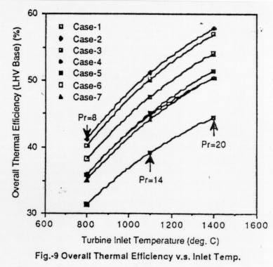
in a study on methanol fuelled gas turbines, the authors have published a figure that shows the increase in thermal efficiency as TET increases.

Increase in thermal efficiency as TET increases, from Asahi-net.

This desire to push the TET as high as possible has lead to several advances in turbine blade cooling. One common technique is to use serpentine flow passages inside the turbine blade. These passages effectively make the turbine blade hollow. Air ducted from compressor outlet flows through these hollow blades. The outer skin of the turbine blade faces the hot combustor exit gases (around 1600 degree Celsius) and the inner skin faces the relatively cooler gas (around 400 degree Celsius). This cooler gas carries some of the heat energy from the hot gases and hence keeps the turbine blade temperature from exceeding its limits.

The problem in implementing these passages in SGT blades is that the blades are too small. Hence it is difficult to machine such intricate passages inside the turbine blade. A figure showing a larger engine's turbine blade and SGT's turbine blade side by side, gives an idea of the level of intricate machining required in SGT blades.
Relative sizes of SGT and large blades, from "The History of North American Small Gas Turbine Aircraft Engines"
The next problem is that of thermal stresses in the turbine disk. As you can see in the image below, the periphery of the turbine disk will be at the temperature of the hot gases. Say 1600 degree celsius. The hub of the turbine disk, where the shaft attaches to the disk, is at a much lower temperature, around 300 degree Celsius.

A turbine disk with blades, from codesmith.com
This difference in temperature causes thermal stresses. The difference in temperature is same for both SGT and large engines, but he distance over which this change in temperature happens is much smaller in a SGT.
This smaller distance gives higher stresses for the same temperature change.

Demonstrating with an example:

The formula for radial stress in a disk of uniform thickness (E = Youngs modulus, α = coefficient of expansion ) is

In the above equation, the constants A and B can be found by imposing the condition that the radial stress has to be 0 at the inner and outer radius. Using this equation, the radial stress distribution of two turbine disks have been computed and plotted below. The temperature at the inner radius of both the disks is 300 degree Celsius and the temperature at the outer radius is 1600 degree Celsius. The SGT disk is smaller, with the inner radius of 3 cm and outer radius of 10 cm. The larger turbine disk has a inner radius of 10 cm and outer radius of 30 cm. The graph below shows the level of radial stress along the radius of the turbine disk.

 
Smaller engines experience higher stresses
 It can be seen that the SGT disk faces higher thermal stresses than the larger turbine disk, though only marginally. In the next article, let us look at the problems faced in the design of the turbine shaft and casings for the small gas turbine.